
LoopDraw: a Loop-Based Autoregressive Model for Shape Synthesis and Editing
- University of Chicago 1
- TTI-Chicago 2
There is no settled universal 3D representation for geometry with many alternatives such as point clouds, meshes, implicit functions, and voxels to name a few. In this work, we present a new, compelling alternative for representing shapes using a sequence of cross-sectional closed loops. The loops across all planes form an organizational hierarchy which we leverage for autoregressive shape synthesis and editing. Loops are a non-local description of the underlying shape, as simple loop manipulations (such as shifts) result in significant structural changes to the geometry. This is in contrast to manipulating local primitives such as points in a point cloud or a triangle in a triangle mesh. We further demonstrate that loops are intuitive and natural primitive for analyzing and editing shapes, both computationally and for users.
Loop Editing Demos
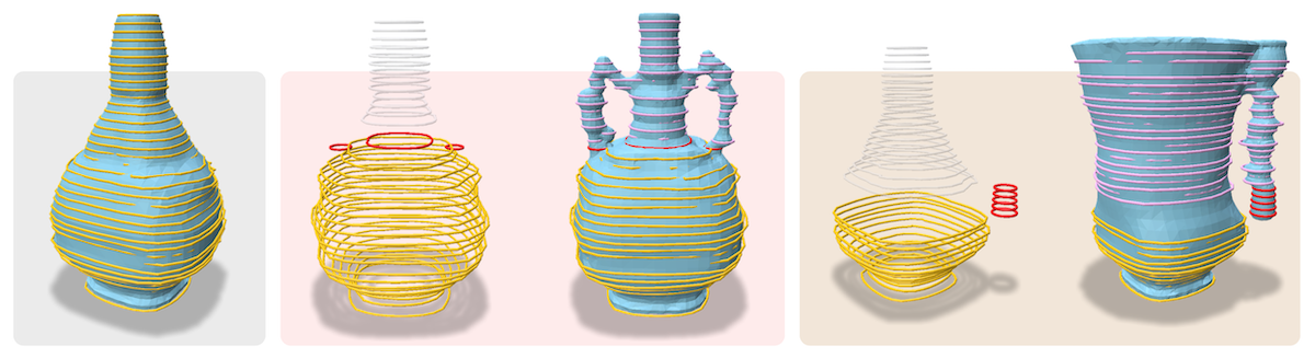
A demonstration of our loop-based shape generation and then editing. loops are auto-regressively decoded (untampered) from a latent code. loops are custom loops manually inserted during auto-regressive decoding. Purple loops are the resulting loop sequence that follows the manual edit.
Slicing Meshes into Loops
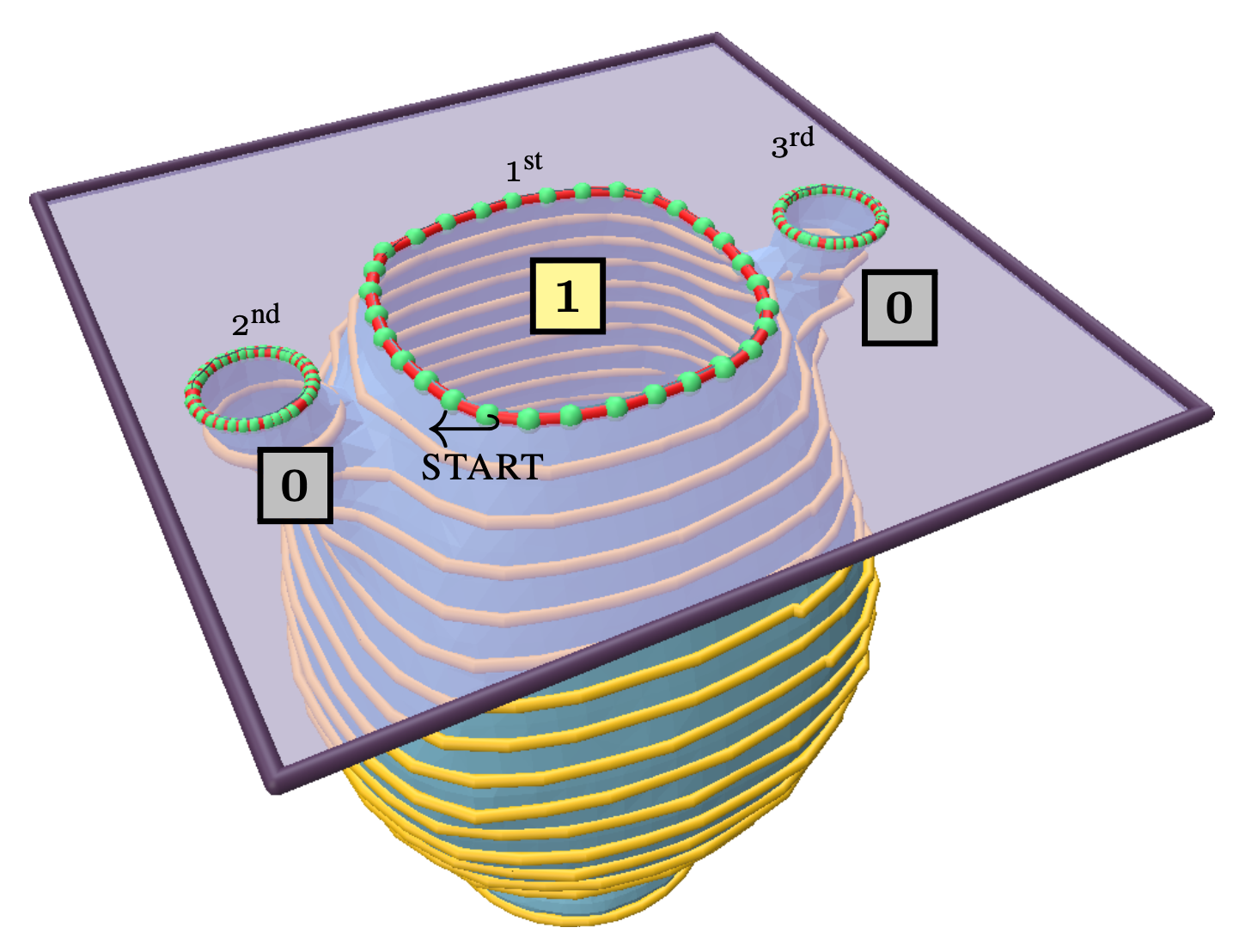
Closeup of a slice plane. In this example, the plane intersects the mesh at three closed loops, defining three time steps in our sequence data. Each loop has an associated level-up binary flag (shown as or ); the loop with a flag introduces this slice plane and comes first in the sequence data, followed by the other loops with a flag of .
Sequence VAE Architecture
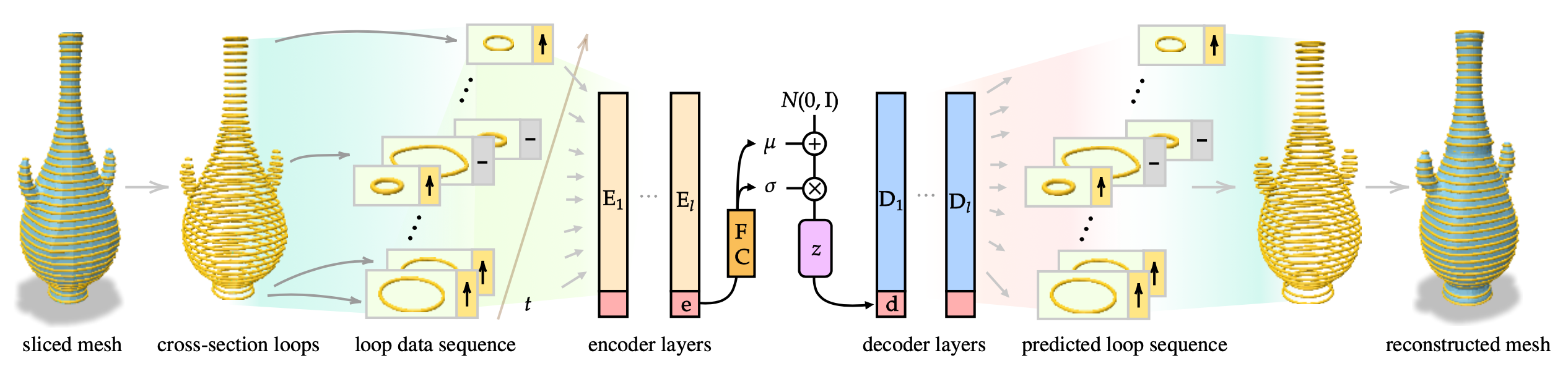
LoopDraw overview. Starting with an initial mesh, we extract a sequence of cross-sectional loops over a progression of planes. The entire sequence of loops (2D polygons with a level-up flag), augmented with a special token , is encoded through a series of transformer layers, producing features . The special token in the last layer's output is used as an aggregate encoder embedding that is then mapped to the parameters of a latent distribution. The latent vector is projected to the start-of-sequence embedding for the decoder, in which transformer layers produce , which is trained to reconstruct the original input loop sequence. The reconstruction loss is the L2 distance (and cross-entropy for the binary flag) between the predicted and ground truth loop data, and a KL divergence term on the latent space parameters. The network-predicted loops are reconstructed to obtain a 3D mesh. In generation mode, we sample from a standard Gaussian, and generate the sequence autoregressively.
Dragging the loops
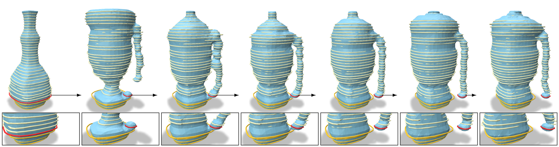
Adaptive shape repair and morphing by the manual editing of a single loop during autoregressive decoding. The original untampered shape is the leftmost figure, showing the original size and position of the target loop in red. The rest of the shapes show decoding results where the target loop (scaled by 0.3) is translated away by increasing amounts (see close-ups in inset figures). To best explain the manually-added anomaly of the shifted loop, the model transitions from decoding a symmetrical, handleless vase to decoding a one-handle vase that accommodates the new target loop position.
Layout inspired by distill.